
K13 PVC Subway Signalling Cables for Metro/Local Trains/Tramlines
Application
The cables are designed for remote control and teletransmission in underground railway networks. The cables can be laid in channel, cable tray, or on hook supports, along suburban railway lines electrifi ed at maximum 1500V DC.
Standards
AFNOR NF F 55-633
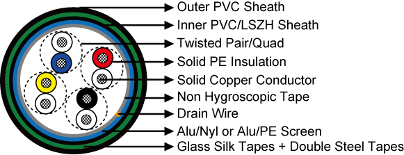
Construction
- Conductors: Solid copper conductor, 0.6/0.8/1.0/1.2 mm nominal diameter.
- Insulation: Polyethylene insulation.
- Cabling Element: Pair/Quad.
- Stranding: 4-pair cables are composed of pairs, while other cables are composed of star quads.
- Spare Pairs: Spare pairs may be provided according to capacity of cables.
- Core Wrapping: One or more non-hygroscopic polyester tapes are helically or longitudinally laid with an overlap.
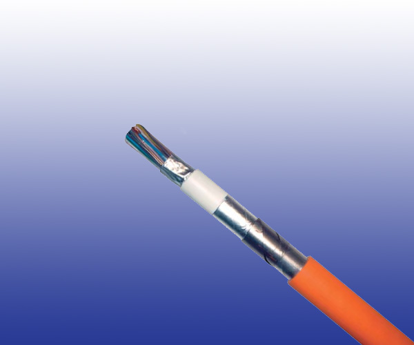
- Screen: Aluminium/Nylon tape bonded with a special PVC sealing sheath or Aluminium/PE tape bonded with a halogen-free fi re-retardant sheath.
- Drain Wire: A tinned copper drain wire, 0.5mm nominal diameter.
- Bedding: Several glass silk tapes are helically laid with an overlap to form bedding.
- Armour: Two helically applied steel tapes.
- Outer Sheath: LSPVC.
Electrical Characteristics at 20℃
| Nominal Conductor Diameter | mm | 0.6 | 0.8 | 1.0 | 1.2 |
| Nominal Mutual Capacity | nF/km | 57.5 | 57.5 | 57.5 | 57.5 |
| Minimum Insulation Resistance | MΩ.km | 5000 | 5000 | 5000 | 5000 |
| Maximum Operating Voltage | V | 200 | 400 | 500 | 750 |
| Maximum Permissible Current | A | 0.35 | 0.63 | 1.0 | 1.4 |
Mechanical and Thermal Properties
- Minimum Bending Radius: 8×OD (static); 16×OD (dynamic)
- Temperature Range: -40℃ to +60℃ (during operation); -20℃ to +50℃ (during installation)
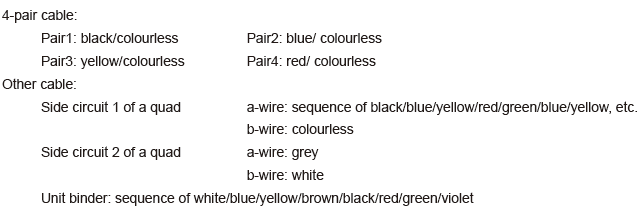
Core Identification
Dimensions and Weight
| Cable Code | Number of Pairs | Nominal Sheath Thickness mm |
Nominal Overall Diameter mm |
Nominal Weight kg/km |
|
| Inner | Outer | ||||
| 0.6mm Conductor, 0.96mm Insulated Wire | |||||
| RS/K13-2Y(L)2YBY-4P0.6 | 4 | 1.0 | 1.0 | 12.5 | 220 |
| RS/K13-2Y(L)2YBY-8P0.6 | 8(4Q) | 1.0 | 1.0 | 13.5 | 260 |
| RS/K13-2Y(L)2YBY-14P0.6 | 14(7Q) | 1.0 | 1.2 | 15.5 | 350 |
| RS/K13-2Y(L)2YBY-28P0.6 | 28(14Q) | 1.0 | 1.4 | 17.5 | 480 |
| RS/K13-2Y(L)2YBY-56P0.6 | 56(4 x 7Q) | 1.0 | 1.4 | 22.0 | 750 |
| 0.8mm Conductor, 1.27mm Insulated Wire | |||||
| RS/K13-2Y(L)2YBY-4P0.8 | 4 | 1.0 | 1.0 | 14.0 | 280 |
| RS/K13-2Y(L)2YBY-8P0.8 | 8(4Q) | 1.0 | 1.2 | 15.0 | 340 |
| RS/K13-2Y(L)2YBY-14P0.8 | 14(7Q) | 1.0 | 1.4 | 18.0 | 470 |
| RS/K13-2Y(L)2YBY-28P0.8 | 28(14Q) | 1.0 | 1.4 | 21.0 | 700 |
| RS/K13-2Y(L)2YBY-56P0.8 | 56(4 x 7Q) | 1.0 | 1.6 | 28.5 | 1200 |
| 1.0mm Conductor, 1.8mm Insulated Wire | |||||
| RS/K13-2Y(L)2YBY-4P1 | 4 | 1.0 | 1.2 | 15.5 | 340 |
| RS/K13-2Y(L)2YBY-8P1 | 8(4Q) | 1.0 | 1.4 | 17.5 | 460 |
| RS/K13-2Y(L)2YBY-14P1 | 14(7Q) | 1.0 | 1.4 | 20.5 | 630 |
| RS/K13-2Y(L)2YBY-28P1 | 28(14Q) | 1.0 | 1.6 | 25.0 | 990 |
| RS/K13-2Y(L)2YBY-56P1 | 56(4 x 7Q) | 1.0 | 1.8 | 34.0 | 1700 |
| 1.2mm Conductor, 2.0mm Insulated Wire | |||||
| RS/K13-2Y(L)2YBY-2P1.2 | 2(1Q) | 1.0 | 1.2 | 12.5 | 240 |
| RS/K13-2Y(L)2YBY-4P1.2 | 4 | 1.0 | 1.4 | 17.0 | 420 |
| RS/K13-2Y(L)2YBY-8P1.2 | 8(4Q) | 1.0 | 1.4 | 18.5 | 530 |
| RS/K13-2Y(L)2YBY-14P1.2 | 14(7Q) | 1.0 | 1.4 | 21.5 | 740 |
| RS/K13-2Y(L)2YBY-28P1.2 | 28(14Q) | 1.0 | 1.6 | 27.5 | 1250 |