
ZPFU & ZPFU-SH Main & Local Signalling Cables (DC Electrified Lines)
Application
The cables are designed for the main signalling circuits of 1500V DC electrifi ed lines.
Standards
- SNCF CT 445
- NF F 55-698
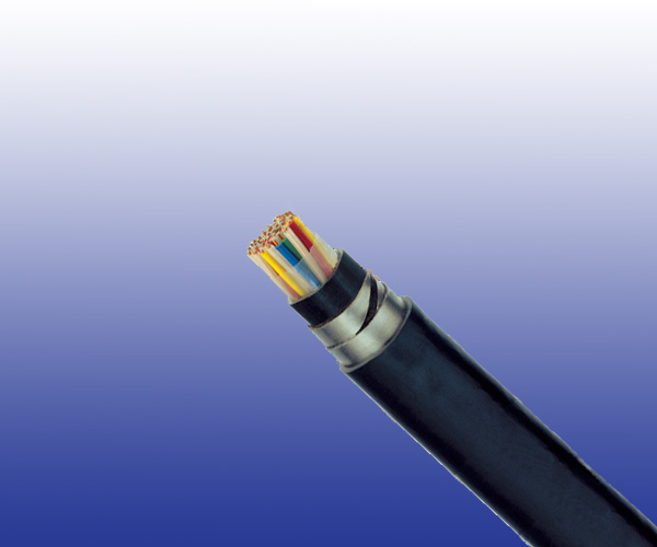
Construction
- Conductors: Solid annealed copper, 1.0mm² nominal cross section area.
- Insulation: Solid polyethylene.
- Cabling Element: Each two conductors are twisted together to form a pair.
- Stranding: Pairs are helically stranded in layers to form the cable core.
- Core Wrapping: Plastic tape(s) with overlapping.
- Inner Sheath: PE sheath. LSZH FR option can be offered upon request to NF C 32 070.2.2 (C1).
- Mechanical Protection: Two helically applied steel tapes (0.15, 0.2/0.5mm, depending on pair count).
- Outer Sheath: PE/PVC. LSZH FR option can be offered upon request to NF C 32 070.2.2 (C1).
- Remark: ZPFU: PE/PVC Sheath; ZPFU-SH: LSZH Sheath.
.png)
Electrical Characteristics at 20℃
| Nominal Conductor Diameter | mm | 1.13 | 1.38 |
| Nominal Cross Section Area | mm² | 1.0 | 1.5 |
| Maximum Conductor Resistance (DC) | Ω/km | 18.1 | 12.31 |
| Minimum Insulation Resistance @500 V DC (3mins) | MΩ.km | 5000 | 5000 |
| Maximum Mutual Capacitance @1000Hz (AC) | nF/km | 55 | 55 |
| Maximum Capacitance Unbalance @1000Hz | pF/500 m | 400 | 400 |
| Attenuation @45KHz | dB/km | 2.5 | 2.5 |
| Characteristic Impedance @45KHz | Ω | 120 | 120 |
| Dielectric Strength, conductor to conductor (DC voltage 3secs) | V | 4500 | 4500 |
| Operating Voltage (AC/DC) | V | 450/750 | 450/750 |
Mechanical and Thermal Properties
Minimum Bending Radius: 8×OD (static); 16×OD (dynamic)
Temperature Range: -40℃ to +70℃ (during operation); -20℃ to +50℃ (during installation)
Dimensions and Weight
| Cable Code | No. of Pairs |
Nominal Sheath Thickness mm |
Nominal Overall Diameter mm |
Nominal Weight kg/km |
Armour Thickness mm |
|
| Inner | Outer | |||||
| 1.13mm Conductor, 2.3 Insulated Wire | ||||||
| RS/ZPFU-2Y2YB2Y-1P1S | 1 | 1.0 | 1.5 | 11.7 | 207 | 0.15 |
| RS/ZPFU-2Y2YB2Y-2P1S | 2 | 1.0 | 1.5 | 12.9 | 257 | 0.2 |
| RS/ZPFU-2Y2YB2Y-4P1S | 4 | 1.0 | 1.6 | 16.8 | 509 | 0.2 |
| RS/ZPFU-2Y2YB2Y-7P1S | 7 | 1.0 | 1.7 | 19.0 | 653 | 0.5 |
| RS/ZPFU-2Y2YB2Y-14P1S | 14 | 1.2 | 1.8 | 24.1 | 1011 | 0.5 |
| RS/ZPFU-2Y2YB2Y-21P1S | 21 | 1.2 | 2.0 | 27.8 | 1304 | 0.5 |
| RS/ZPFU-2Y2YB2Y-28P1S | 28 | 1.2 | 2.2 | 31.0 | 1594 | 0.5 |
| RS/ZPFU-2Y2YB2Y-56P1S | 56 | 1.3 | 2.5 | 40.5 | 2630 | 0.5 |